Citizens Band (CB) radio has been a reliable communication tool for truckers, hobbyists, and emergency responders for decades. At the heart of any effective CB setup lies the coaxial cable, the vital conduit that transmits radio signals between your transceiver and antenna. However, like any electronic component, coaxial cables can develop issues that degrade performance, leading to frustratingly weak signals, static-filled transmissions, or complete communication blackouts. This article delves into the most common problems plaguing CB coaxial cables and provides a step-by-step guide to troubleshooting them, ensuring your CB stays operational when you need it most.
Understanding the Anatomy of CB Coaxial Cable
Before we can effectively troubleshoot, it’s crucial to understand the basic construction of a coaxial cable. Most CB coaxial cables consist of several key components:
- Center Conductor: This is typically a solid or stranded copper wire that carries the actual radio signal.
- Dielectric Insulator: A non-conductive material (often polyethylene) that surrounds the center conductor, maintaining a consistent distance between it and the outer conductor. This spacing is critical for impedance matching.
- Outer Conductor (Shield): Usually a braided copper mesh or foil, this layer acts as a ground and shields the signal from external interference.
- Outer Jacket: A protective layer of PVC or other durable material that shields the cable from environmental damage and abrasion.
- Connectors: Typically PL-259 (male) and SO-239 (female) connectors, which allow for easy connection and disconnection of the cable to the radio and antenna.
The impedance of a CB coaxial cable is almost universally 50 ohms. Any deviation from this impedance, often caused by damage or faulty connectors, can lead to significant signal loss and standing wave ratio (SWR) issues.
The Most Common Culprits: Identifying Cable Problems

When your CB signal weakens or disappears, the coaxial cable is a prime suspect. Here are the most frequently encountered issues:
1. Damaged Connectors: The Achilles’ Heel of Coax

Connectors are frequently handled, exposed to the elements, and subjected to mechanical stress, making them highly prone to damage. Common connector problems include:
- Corrosion: Salt, moisture, and environmental pollutants can corrode the metal parts of the connector, creating poor electrical contact and high resistance. This is a particularly prevalent issue in vehicles exposed to road salt or in marine environments.
- Loose or Bent Center Pin: If the center pin of a PL-259 connector is bent or not making proper contact with the SO-239 socket on the radio or antenna, it will severely impede signal flow.
- Cracked or Damaged Insulator: The dielectric material within the connector can crack or degrade, leading to impedance mismatches and signal leakage.
- Improperly Crimped or Soldered Connections: A poorly executed connection at the connector can result in intermittent signals, high SWR, and eventual failure. Statistics from amateur radio forums and CB repair shops often point to connector issues as the cause of 40-50% of coax-related problems.
2. Cable Kinks, Bends, and Physical Damage
Coaxial cable, while flexible, has its limits. Sharp bends or kinks can physically deform the cable, disrupting the consistent spacing between the center conductor and the shield. This disruption creates impedance mismatches and signal attenuation. Examples include:
- Sharp Bends at Entry Points: Forcing the cable through tight openings in vehicle bodies or mounting brackets can create acute angles.
- Cable Under Tension: If the cable is stretched taut, it can pull on connectors or weaken internal connections.
- Abrasion and Cuts: Rubbing against sharp metal edges, road debris, or during installation can cut through the outer jacket, exposing the shield and potentially the dielectric.
3. Water Intrusion and Corrosion Within the Cable
Moisture is the sworn enemy of coaxial cable. When water seeps into the cable, typically through damaged outer jackets or poorly sealed connectors, it can:
- Corrode the Center Conductor and Shield: Leading to increased resistance and signal loss.
- Degrade the Dielectric: Altering the cable’s electrical properties and causing impedance mismatches.
- Promote Oxidation: Further hindering conductivity.
A classic case study involves a truck driver who experienced intermittent radio silence for weeks. Upon inspection, the coaxial cable, routed under the chassis, had a small abrasion. Water had wicked up the cable over time, causing extensive corrosion that eventually rendered the entire cable useless.
4. Internal Cable Degradation and Aging
Over time, the materials within a coaxial cable can degrade due to UV exposure, extreme temperatures, and general wear and tear. The dielectric can become brittle, and the copper conductors can oxidize, even without visible external damage. This gradual deterioration leads to increasing signal loss (attenuation).
5. Impedance Mismatches: The Invisible Killer of Performance

As mentioned, CB systems are designed for a 50-ohm impedance. Any component in the transmission line that deviates from this – including damaged cables, connectors, or an improperly matched antenna – will cause a portion of the radio signal to be reflected back towards the transmitter. This is measured as the Standing Wave Ratio (SWR).
- High SWR: Indicates a significant impedance mismatch. A high SWR not only reduces the power transmitted to the antenna but can also damage the radio’s final amplifier stage due to reflected power. Typical CB radios are designed to operate with an SWR below 1.5:1. Anything above 2.0:1 is generally considered problematic.
- Causes of Mismatch: Damaged dielectric, kinked cables, corroded connectors, or an incorrect antenna type.
Troubleshooting Your CB Coaxial Cable: A Practical Approach

When faced with CB communication issues, a systematic approach to troubleshooting the coaxial cable is essential. Here’s how to tackle it:
Step 1: Visual Inspection – The First Line of Defense
Begin with a thorough visual examination of the entire length of the coaxial cable and its connectors. Look for:
- Obvious damage: Cuts, abrasions, melted sections, or kinks.
- Connector integrity: Check for bent center pins, cracked insulators, or signs of corrosion (greenish or whitish powdery residue).
- Secure connections: Ensure both ends of the cable are firmly attached to the radio and antenna.
- Cable routing: Observe how the cable is routed. Is it pinched, under excessive tension, or rubbing against anything sharp?
Example: On a truck, pay close attention to areas where the cable passes through firewalls, along the chassis, or near exhaust pipes, which can cause heat damage.
Step 2: Test Connectors – The Most Common Weak Link
If visual inspection doesn’t reveal a clear culprit, focus on the connectors. For a more in-depth check:
- Disconnect and Reconnect: Gently disconnect and then firmly reconnect both ends of the coaxial cable. Sometimes, a loose connection is the only issue.
- Clean Connectors: If you see any signs of corrosion or dirt, use a contact cleaner and a small brush to clean the connector pins and sockets. For stubborn corrosion, a pencil eraser can sometimes be used to gently buff the contact surfaces.
- Inspect Center Pin Alignment: With the connector disconnected, carefully examine the center pin of the PL-259 connector. It should be straight and aligned with the connector body. If it’s bent, you might be able to *very carefully* straighten it with needle-nose pliers, but often replacement is the better option.
Step 3: Check for Continuity and Shorts – The Electrical Test

This step requires a multimeter. You’ll be testing for electrical continuity (a complete circuit) and shorts (unintended connections).
- Continuity Test (Center Conductor): Set your multimeter to the resistance (Ohms) setting or continuity beeper. Touch one probe to the center pin of one end of the coaxial cable and the other probe to the center pin of the other end. You should get a very low resistance reading (close to zero) or hear a continuous beep, indicating good continuity.
- Continuity Test (Shield): Next, touch one probe to the outer metal body (shield) of one connector and the other probe to the outer metal body of the other connector. Again, you should get a very low resistance reading or a beep.
- Short Test (Center to Shield): Now, touch one probe to the center pin of one connector and the other probe to the outer metal body of the *same* connector. You should get an open circuit reading (OL or infinite resistance) – no beep. Repeat this for the other end of the cable. If you get a beep or low resistance, it means the center conductor is shorting to the shield, indicating a serious internal cable problem.
Statistics: In a study by a popular CB accessory manufacturer, over 60% of returned coaxial cables were found to have minor to moderate connector damage or internal shorts.
Step 4: Measure Standing Wave Ratio (SWR) – The Performance Indicator
The SWR meter is an indispensable tool for diagnosing coaxial cable problems and overall antenna system performance. An SWR meter is placed in-line between your CB radio and the coaxial cable connecting to the antenna.
Procedure:
- Connect the SWR Meter: Disconnect the coaxial cable from your CB radio and connect it to the “ANT” (Antenna) port of the SWR meter. Connect a short jumper cable from the “XMIT” (Transmitter) port of the SWR meter to the antenna connector on your CB radio.
- Tune to Mid-Band: Turn your CB radio on and select a channel in the middle of the band (e.g., channel 20).
- Transmit Briefly: Press and hold the transmit button on your microphone.
- Read the SWR: Observe the SWR meter. Most meters have a “SET” or “CAL” position to calibrate the meter, followed by a “SWR” or “READ” position. Follow your meter’s instructions.
- Check Multiple Channels: Repeat the process on the lowest (channel 1) and highest (channel 40) channels.
Interpretation:
- High SWR on All Channels: This strongly suggests a problem with the coaxial cable or the antenna itself. If the SWR is consistently high across the entire band, the cable is a likely culprit, especially if it shows signs of damage or fails continuity tests.
- SWR Varies Significantly by Channel: This often points to an antenna tuning issue, but a damaged cable can also contribute to this by introducing variable impedance.
- Low SWR on Some Channels, High on Others: This is typical of an antenna mismatch. However, if the SWR is high *even on the resonant frequency of the antenna*, then the cable becomes a primary suspect.
Case Study: A mobile CB user reported a very weak outgoing signal. Their SWR meter showed an SWR of 3.5:1 on channel 1 and 4.0:1 on channel 40. A visual inspection revealed that the coaxial cable, routed near the engine, had a melted section from heat exposure. Replacing the damaged cable brought the SWR down to a respectable 1.2:1.
Step 5: Substitute Known Good Components – The Isolation Technique
If you’ve performed the above steps and are still uncertain, the best troubleshooting method is to isolate the variable. This involves swapping out components with ones you know are working correctly:
- Swap the Coaxial Cable: If possible, connect a completely different, known-good coaxial cable between your radio and antenna. If the problem disappears, you’ve definitively identified the faulty cable.
- Swap the Antenna: While this article focuses on cables, a faulty antenna can mimic cable issues. If you have a spare antenna, try swapping it out.
- Swap the Radio: In rare cases, a radio issue can manifest as poor transmission. If you have access to another radio, test it.
Preventative Measures: Keeping Your Coax Healthy
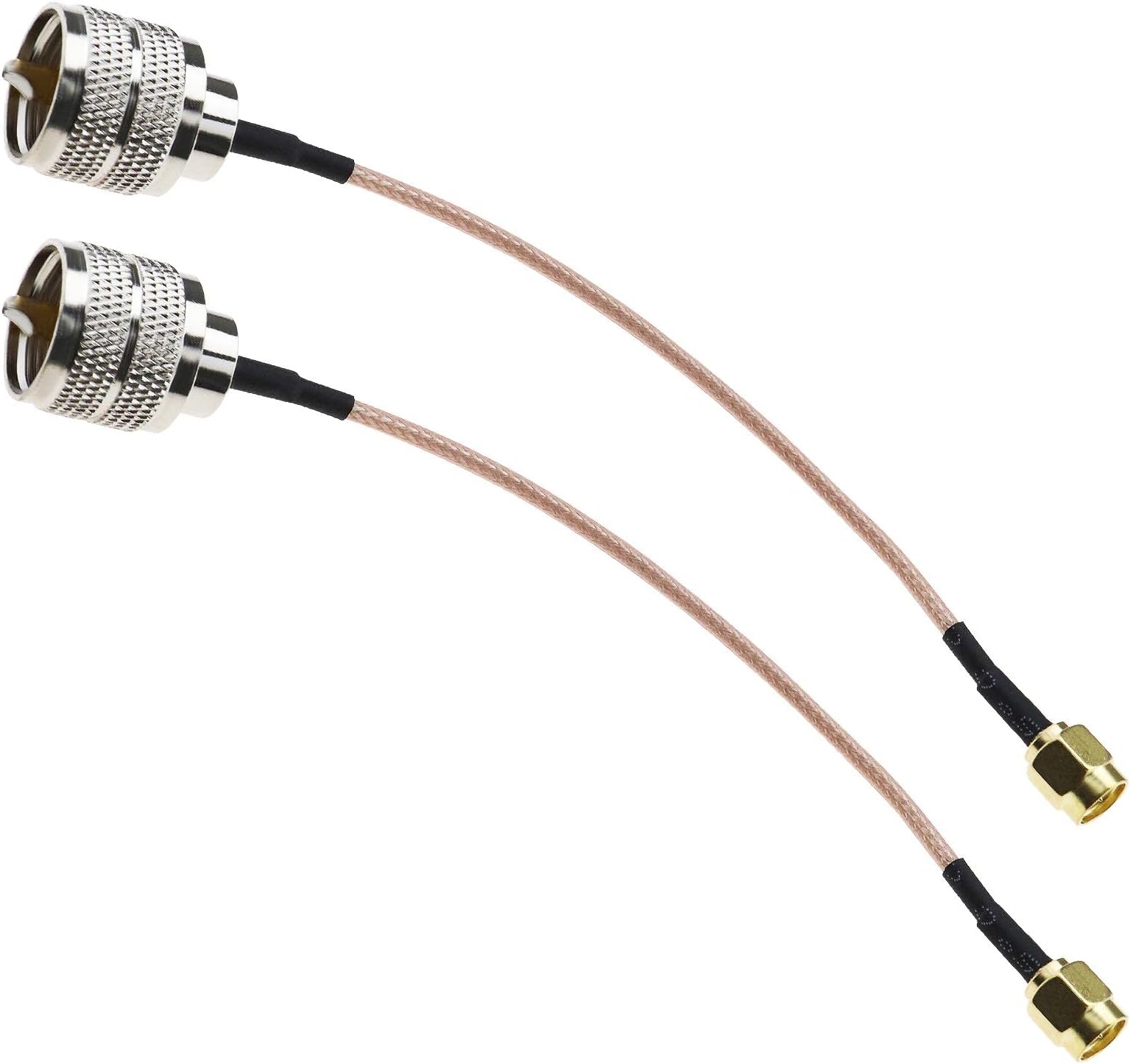
Preventing cable problems is far easier and less frustrating than troubleshooting them. Implement these preventative measures:
- Use Quality Components: Invest in reputable brands of coaxial cable and connectors. Cheaper alternatives often use inferior materials that degrade faster.
- Proper Installation: Avoid sharp bends, kinks, and excessive tension. Secure the cable to prevent it from dangling or rubbing against sharp edges.
- Weatherproof Connections: Use weatherproof boots or tape to seal coax connections, especially in outdoor or mobile installations, to prevent moisture ingress.
- Regular Inspection: Periodically inspect your coaxial cable and connectors for any signs of wear, damage, or corrosion.
- Strain Relief: Ensure connectors are not bearing the full weight of the cable. Use cable ties or mounts to support the cable.
Restoring Your CB’s Voice
A functional coaxial cable is paramount to a reliable CB communication system. By understanding the common failure points – from corroded connectors and physical damage to internal degradation and impedance mismatches – and employing a systematic troubleshooting approach, you can effectively diagnose and resolve most issues. Visual inspection, connector checks, electrical continuity tests, and SWR measurements are your primary tools. Don’t underestimate the power of substituting known good components to isolate the problem. By implementing preventative measures and investing a little time in diagnostics, you can ensure your CB radio continues to be a dependable companion for communication, whether on the open road or in your favorite outdoor pursuits.